
How do you make sure that your data is clean and consistent?
One great way is through the use of Attribute Rules.
There is a great tutorial in the ArcGIS Pro Documentation. Here is the data: Data Reviewer for ArcGIS Pro Tutorial
- Methods to implement automated review—ArcGIS Pro | Documentation
- Enhance quality assurance during editing—ArcGIS Pro | Documentation
- Evaluate features with attribute rules—ArcGIS Pro | Documentation
If you are looking for more, here are some great notes from Penn State’s Spatial Database Management Course: Attribute Domains | GEOG 868: Spatial Databases (psu.edu)
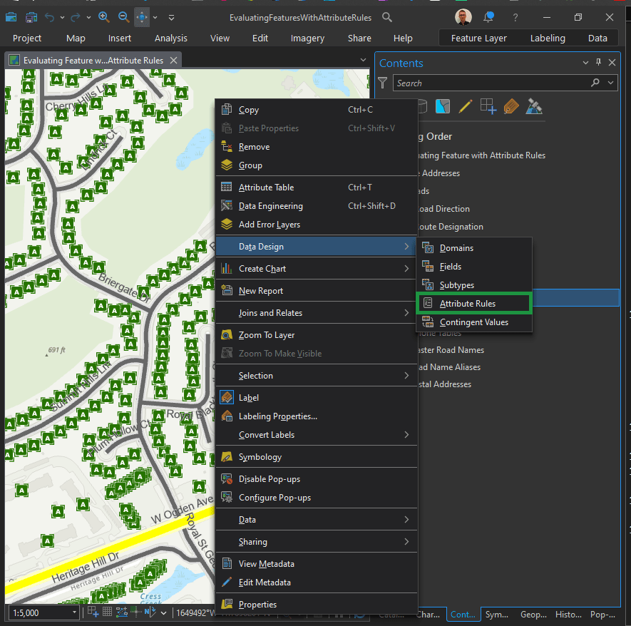
Right click on the desired layer in the Contents Pane. Next, Data Design > Attribute Rules (as seen above).
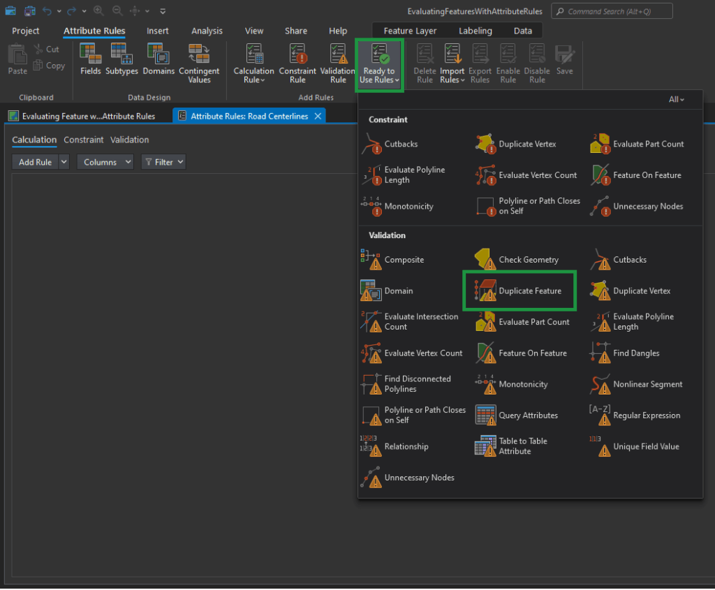
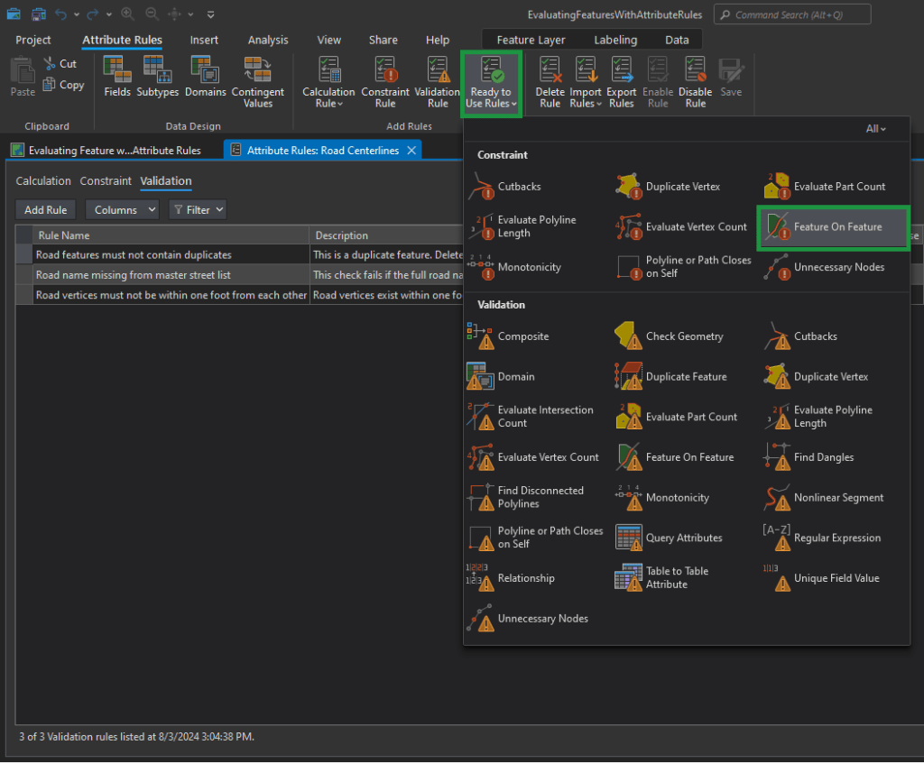
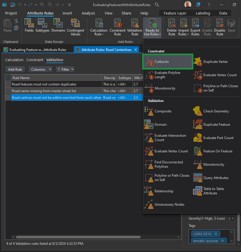
Now in the top Menu Ribbon, choose the Attribute Rules tab. You have a lot to choose from. Let’s explore “Ready to Use Rules” first.

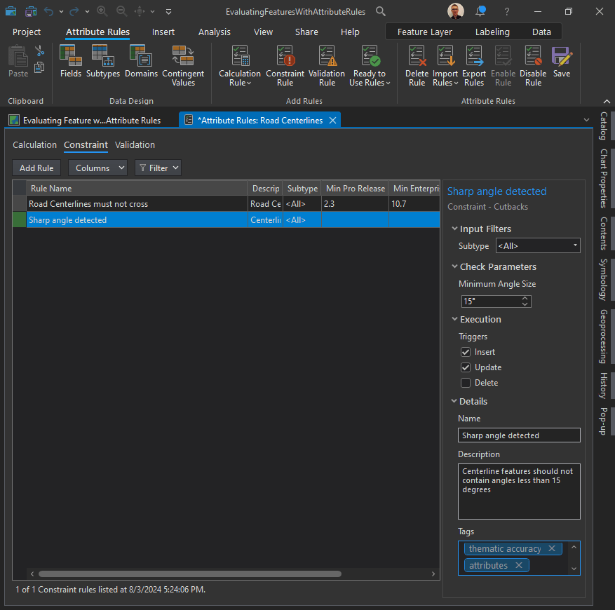
Tags can be used to enable requirements traceability. Consider including the data model and version that the rule is related to or including an ISO-19157 data quality element, such as thematic accuracy.
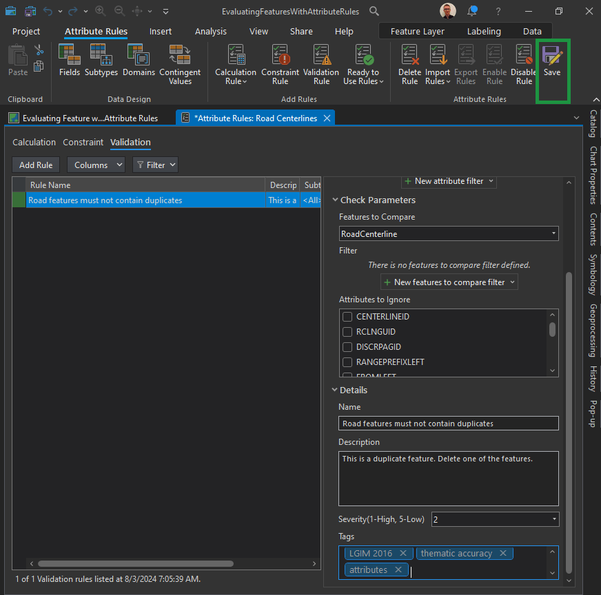
For this rule, we can enter the following:
- Name: Road features must not contain duplicates
- Description: This is a duplicate feature. Delete one of the features.
- Tags: thematic accuracy, attributes
ISO 19157:2013 Geographic information – Data quality:
ISO 19157:2013 establishes the principles for describing the quality of geographic data. It defines components for describing data quality; specifies components and content structure of a register for data quality measures; describes general procedures for evaluating the quality of geographic data; and establishes principles for reporting data quality.
The standard also defines a set of data quality measures for use in evaluating and reporting data quality. It is applicable to data producers providing quality information to describe and assess how well a dataset conforms to its product specification and to data users attempting to determine whether or not specific geographic data are of sufficient quality for their particular application.
The standard does not attempt to define minimum acceptable levels of quality for geographic data.
Implementation guidelines
According to ISO 19157:2013, data quality comprises six elements: completeness, thematic accuracy, logical consistency, temporal quality, positional accuracy and usability.
Each element is comprised of a number of sub-elements, for example, completeness (commission and omission), logical consistency (conceptual, domain, format, topological), etc.
These elements are used to describe data quality, i.e. how well a specific dataset meets the criteria for the different elements set forth in its product specification or user requirements.
Evaluation against the criteria is done either quantitatively or subjectively (non-quantitatively). The latter case applies if a detailed data product specification does not exist or if the data product specification lacks quantitative measures and descriptors.
Three “metaquality elements” – confidence, ‘representativity’ and homogeneity – provide quantitative and qualitative statements about the evaluation against the criteria and its result.
Quality information can be provided for different units of data, e.g. a dataset series, a dataset or a subset of a dataset with common characteristics. A data quality unit comprises of a scope and data quality elements. The scope specifies the extent, spatial and/or temporal and/or common characteristic(s) of the unit for which the quality information is provided.
In ISO 19157:2013, quality related information provided by purpose, usage and lineage of geographic data conforms to ISO 19115-1:2014 Geographic information – Metadata – Part 1: Fundamentals.
Conformance Classes:
ISO 19157:2013 specifies four conformance classes, i.e. the standard can be implemented for four different quality aspects of geographic datasets, each briefly described below.
1. Implementing a data quality evaluation process conforming to ISO 19157:2013
A data quality evaluation process conforming to ISO 19157:2013 comprises of four steps:
- Step 1 – Specify the data quality units to be evaluated. Study the data product specification to identify applicable data quality units and their scope. For each data quality unit, identify the applicable data quality element(s). See example in Example: Data quality units.
- Step 2 – Specify the data quality measures to be used to describe quality of each data quality element of a data quality unit. The requirements in the data product specification provide guidance on applicable data quality measures. See example in Example: Data quality measures. The data quality measures in the table are from the list of standardized data quality measures in ISO 19157:2013. It is also possible to describe user-defined quality measures, see further below, and to maintain a collection of such measures in a catalogue or register.
- Step 3 – Specify the data quality evaluation procedures, i.e. the evaluation method(s) to be applied. The method can be direct (based on inspection of the items in the dataset) or indirect (based on external knowledge, such as lineage metadata). Direct evaluation is further classified by the source against which the evaluation is done: internal if only the data in the dataset is evaluated or external if there is reference to external data (e.g. satellite imagery or ground truth). ISO 19157:2013 includes guidance on how to sample data for evaluation.
- Step 4 – Determine the output of the data quality evaluation, i.e. perform the data quality evaluation described in Steps 1-3 above. Additional results may be produced by aggregating or by deriving from existing results without carrying out a new evaluation. How to report the results of the data quality evaluation is described elsewhere in this chapter.
| Data quality unit | Scope | Data quality elements |
| Topographic dataset | All features in the dataset | Completeness (commission and omission), thematic accuracy (correct classification) |
| Street network | Street features in the entire dataset | Logical inconsistency (topological inconsistency) |
| Data quality unit | Data quality element | Data quality measure | Method |
| Topographic dataset | Completeness (commission) | Measure 1: Excess item Measure 2: Number of excess items Measure 3: Number of duplicate feature instances | Direct external Direct external Direct internal |
| Topographic dataset | Completeness (omission) | Measure 1: Missing item Measure 2: Number of missing items | Direct external Direct external |
| Topographic dataset | Thematic accuracy (correct classification) | Measure 1: Number of incorrectly classified features Measure 2: Misclassification rate | Direct external Direct external |
| Street network | Logical inconsistency (topological inconsistency) | Measure 1: Number of missing connections due to undershoots Measure 2: Number of missing connections due to overshoots Measure 3: Number of invalid self-intersect errors Measure 4: Number of invalid self-overlap errors | Direct internal Direct internal Direct internal Direct internal |
2. Implementing data quality metadata conforming to ISO 19157:2013
Data quality metadata describes the quality of geographic data. ISO 19157:2013 specifies a conceptual model of the different components to be used when describing the quality of geographic data. Overview of the components to be used to describe data quality provides and overview of the components and their relationships to each other. A data dictionary, including definitions for all the components, is provided in the standard. Data quality metadata conforming to ISO 19157:2013 conforms to this conceptual model and is reported in conformance with ISO 19115:2003 Geographic information – Metadata and ISO 19115-2:2009 Geographic information – Metadata – Part 2: Extensions for imagery and gridded data
Overview of the components to be used to describe data quality (Source: ISO 19157:2013)
3. Implementing data quality reports conforming to ISO 19157:2013
The first (and obvious) requirement is that the quality report comprises quality metadata conforming to ISO 19157:2013 (see 2. above), i.e. it includes sections on all appropriate aspects of quality and the description of components follow the rules defined in the standard. Additional information can be added to the report, but the structure of the report is not prescribed. Example: Section of a data quality report is an example of a section of a data quality report for the quality evaluation process described above.
| Data quality unit | Data quality element | Data quality measure | Result |
| Topographic dataset | Completeness (commission) | Measure 2: Number of excess items Measure 3: Number of duplicate feature instances | 153 1,036 |
| Topographic dataset | Completeness (omission) | Measure 2: Number of missing items | 697 |
| Topographic dataset | Thematic accuracy (correct classification) | Measure 1: Number of incorrectly classified features Measure 2: Misclassification rate | 8,774 10% |
| Street network | Logical inconsistency (topological inconsistency) | Measure 1: Number of missing connections due to undershoots Measure 2: Number of missing connections due to overshoots Measure 3: Number of invalid self-intersect errors Measure 4: Number of invalid self-overlap errors | 139 57 11 6 |
4. Implementing data quality measures conforming to ISO 19157:2013
A data quality measure conforming to ISO 19157:2013 is structurally and semantically well defined and described and modelled as specified in the standard. Such a measure is described by at least an identifier, a name, an element name, definition and a value type. Optional descriptors are an alias, description, a value structure, example, a basic measure and one or more source references and/or parameters. Note that full inspection is most appropriate for small populations or for tests that can be accomplished by automated means. For larger populations, checking a representative part of the data and reporting the quality result as a percentage rate is more appropriate and practical.
See also
- ISO 19115-1:2014 Geographic information – Metadata – Part 1: Fundamentals
- ISO 19115-2:2009 Geographic information – Metadata – Part 2: Extensions for imagery and gridded data
- ISO 19158:2012 Geographic information – Quality assurance of data supply
Duplicate Vertices:
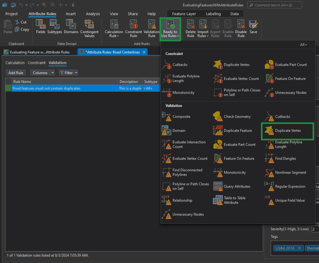
- Name: Road vertices must not exist within one foot from each other
- Description: Road vertices exist within one foot from each other. Update the vertices to be more than one foot apart.
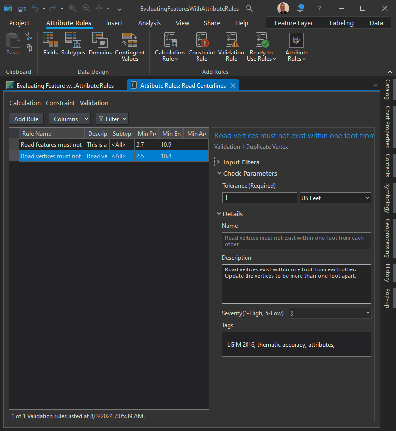
Table to Table Attribute check
The requirement, road centerline Full Road Name attribute values must match the master street index, is implemented with the Table to Table Attribute check to find local roads that contain road name values that are not found in an authoritative list of road names for the municipality.
First, we must configure a filter on the Road Centerlines feature class so that validation will only return results on roads that are local.
In the Input Filters section, click New attribute filter.
Construct the following clause:
<Road Class> <is equal to> <Local-Local> Click “Verify the SQL expression is valid” to validate the SQL expression. Click Apply.
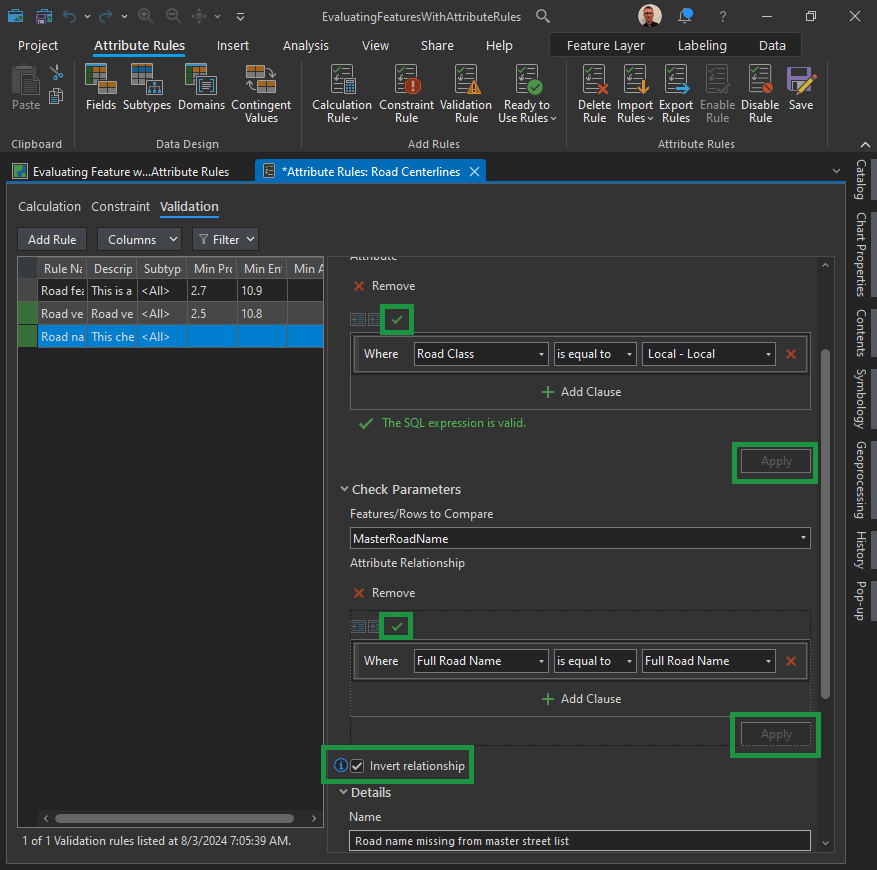
In the Check Parameters section, create the relationship between the Master Road Name feature class and the full road name.
Click the Features to Compare drop-down arrow and click MasterRoadName. Click New attribute relationship and construct the following SQL query:
<Full Road Name> <is equal to> <Full Road Name>Click Verify the SQL expression is valid to validate the SQL expression. Click Apply.
Important! Check the Invert relationship check box to find scenarios where the master road name doesn’t match the full road name.
Constraint attribute rules:
Constraint rules are used to assess a feature’s geometric integrity, spatial relationships with other features, and attribute consistency.
Let’s say you want to implement the following constraints to support address-finding workflows:
| ID | Requirement | Check | Participating feature class/table |
|---|---|---|---|
| 1 | Road centerline must split at an intersection. | Feature on Feature | Road Centerline |
| 2 | Road centerline must not have sharp angles of 15 degrees or less. | Cutbacks | Road Centerline |
| 3 | Road length must be greater than 20 feet. | Evaluate Polyline Length | Road Centerline |
Let’s set up the ID1 Constraint:
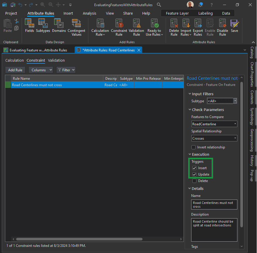
- Check the Insert check box to validate features when they are created.
- Check the Update check box to validate existing features when they are edited.
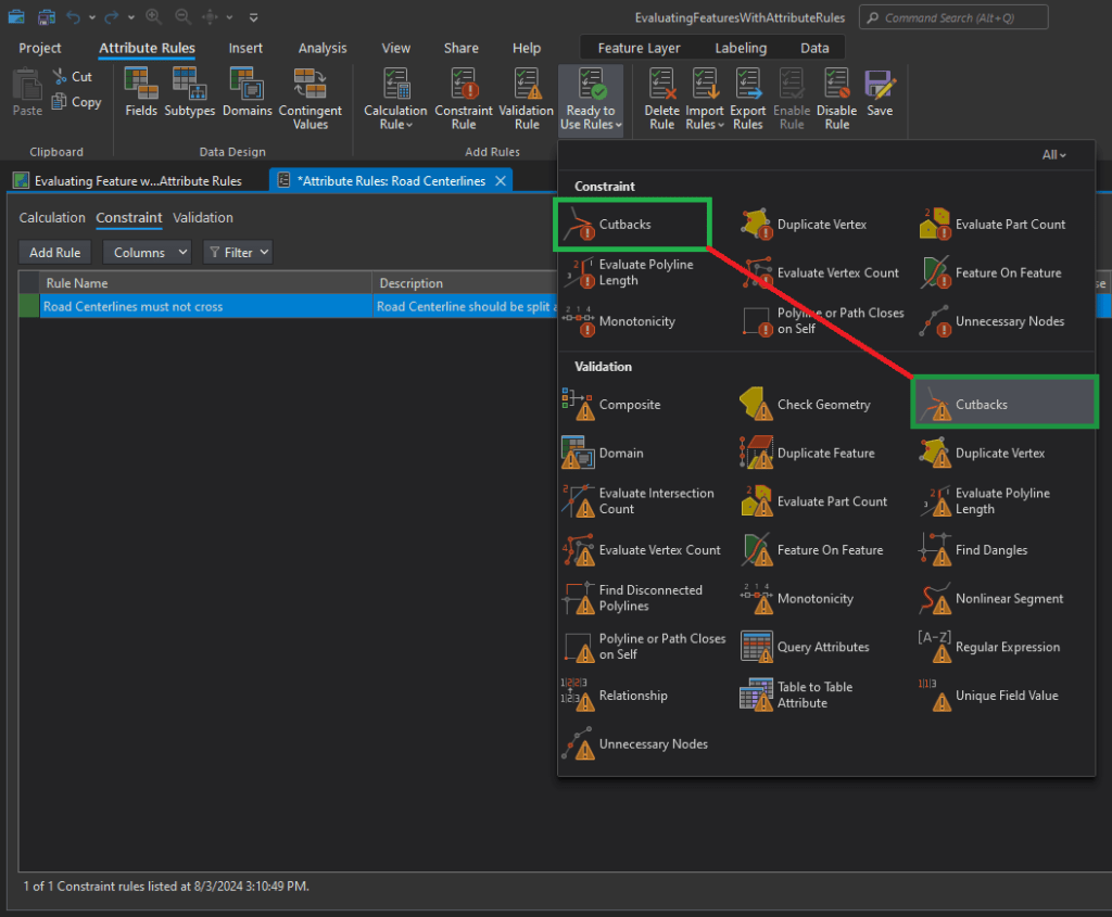
Implement the Cutbacks check:
What are cutbacks?
The Cutbacks check finds polyline or polygon features that contain high-angle turns that cause features to turn back toward themselves.
Notice that “Cutbacks” are found both in the Validation and Constraint sections. We want to choose the one in the “Constraint” section.
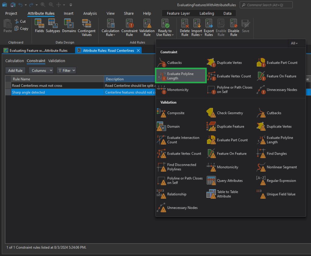
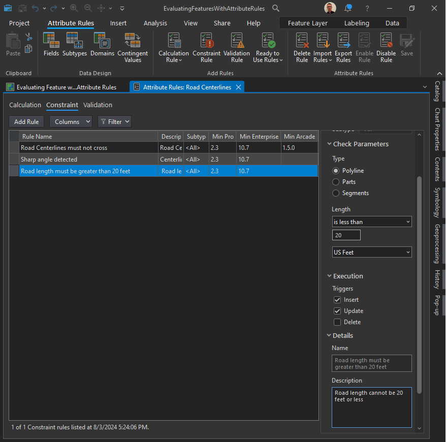
Evaluate Polyline Length check:
Road length must be greater than 20 feet. This requirement is implemented using the Evaluate Polyline Length check to find road centerline features that are 20 feet or smaller.
In the New Evaluate Polyline Lenth Rule pane, in the Check Parameters section, configure the parameters that specify the error condition to be detected.
Click the Length drop-down arrow and choose the is less than option to find roads that are less than 20 feet.
Type 20 in the text box.
Change the unit of measurement to US Feet. This unit of measurement matches the spatial reference of the data.
In the Execution section, configure the parameter that controls when a feature is evaluated during an editing workflow.
- Check the Insert check box to validate features when they are created.
- Check the Update check box to validate existing features when they are edited.
In the Details section, configure the parameters that facilitate corrective workflows and rule management.
Type “Road length must be greater than 20 feet” in the Name text box.
Type “Road length cannot be 20 feet or less” in the Description text box.
Type “thematic accuracy” and “attributes” in the Tags text box.
On the Attributes Rules tab, in the Attributes Rules group, click Save to save the new rules.
Error Inspector:
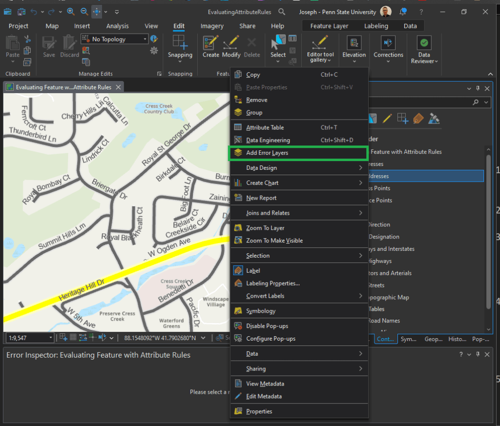
On the Edit tab, in the Manage Edits group, click Error Inspector.

In the Contents pane, right-click any layer in the Site Addresses or Roads group, and click Add Error Layers.
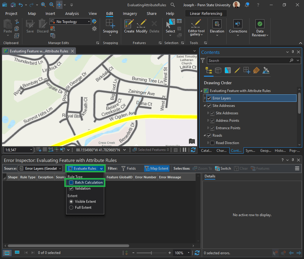
In the Error Inspector pane, click the Evaluate Rules drop-down arrow and uncheck the Batch Calculation check box. Note: Don’t click directly on the “Evaluate Rules” button, we will do that in the next step – but first we need to alter the parameters).
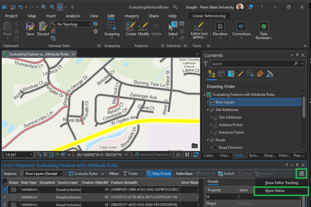
Now click directly on the Evaluate Rules button. It will process for a moment and then errors will appear as rows in the Error Inspector pane.
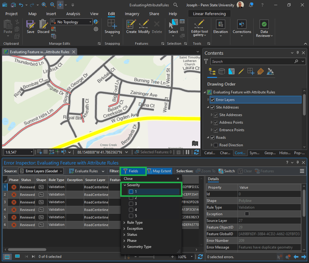
Click the menu button on the Error Inspector toolbar and click Show Status.
The Data Reviewer error life cycle columns are added to the Error Inspector pane.
In the Filter group, click Fields to display a list of error properties that can be used to filter the errors displayed in the Error Inspector pane. In the Severity section, check the 1 check box to only display features with a severity value of 1 in the Error Inspector pane.
Click the numbered column next to the error phase column to highlight the feature that has the error. On the Edit tab, click Attributes to open the Attributes pane.
Can you spot the mistake in “Summit Hills Lm?” Change “Lm” to “Ln.”
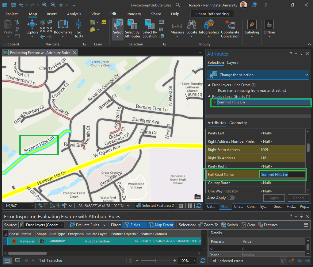
Click Select By Rectangle and drag a rectangle across the road in the map with the error to select it.
In the attributes, scroll to Full Road Name and change Lm to Ln, and press Enter.
In the Attrribute Pane, click Apply.
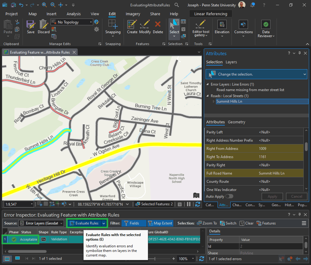
In the Edits ribbon menu, click Save Edits.
Click the Evaluate Rules button. It will now appear with a green check and “Acceptable” status.
Validate features with constraint attribute rules:
Remember requirement ID 3?
| 3 | Road length must be greater than 20 feet. | Evaluate Polyline Length | Road Centerline |
- On the Edit tab, click Create Features.
- The Create Features pane appears.
- Click the Roads: Local Streets template in the Create Features pane.
Draw a small road in the map, less than 20 feet.
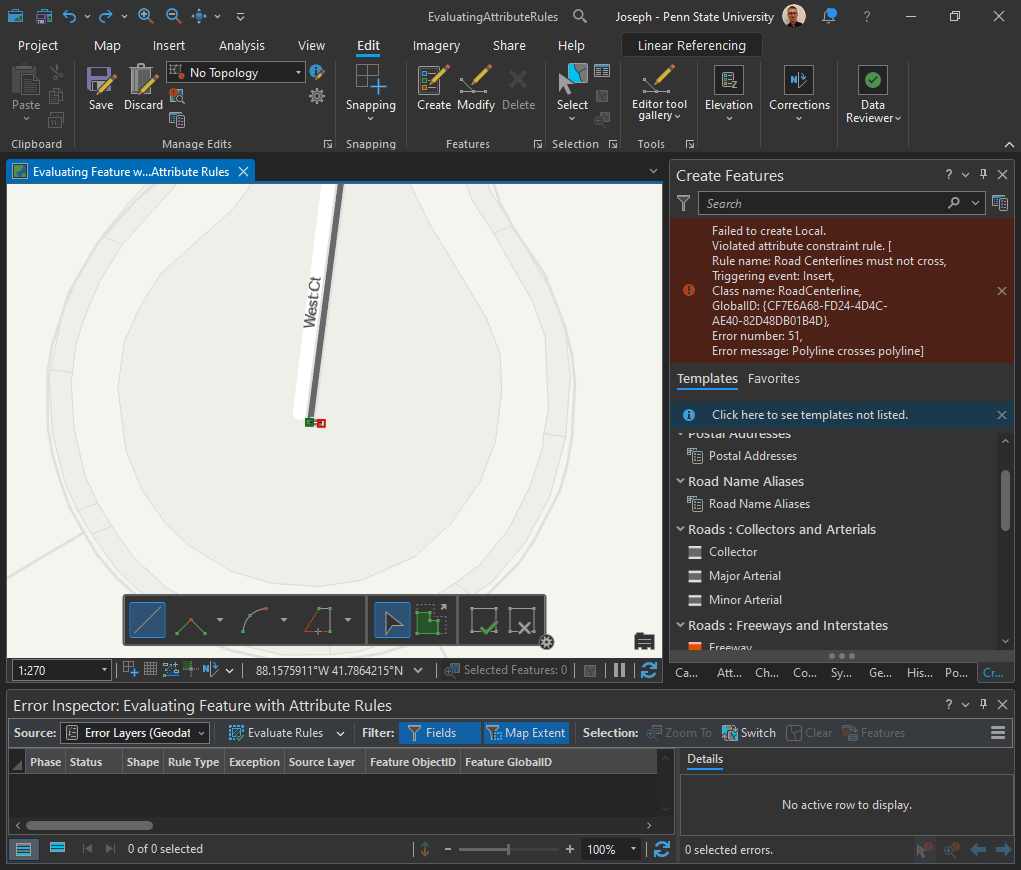
Click Save Edits on the Edit tab and click Yes to save your edits.
The Error results to validate your data using configured checks implemented using attribute rules.

Leave a comment