
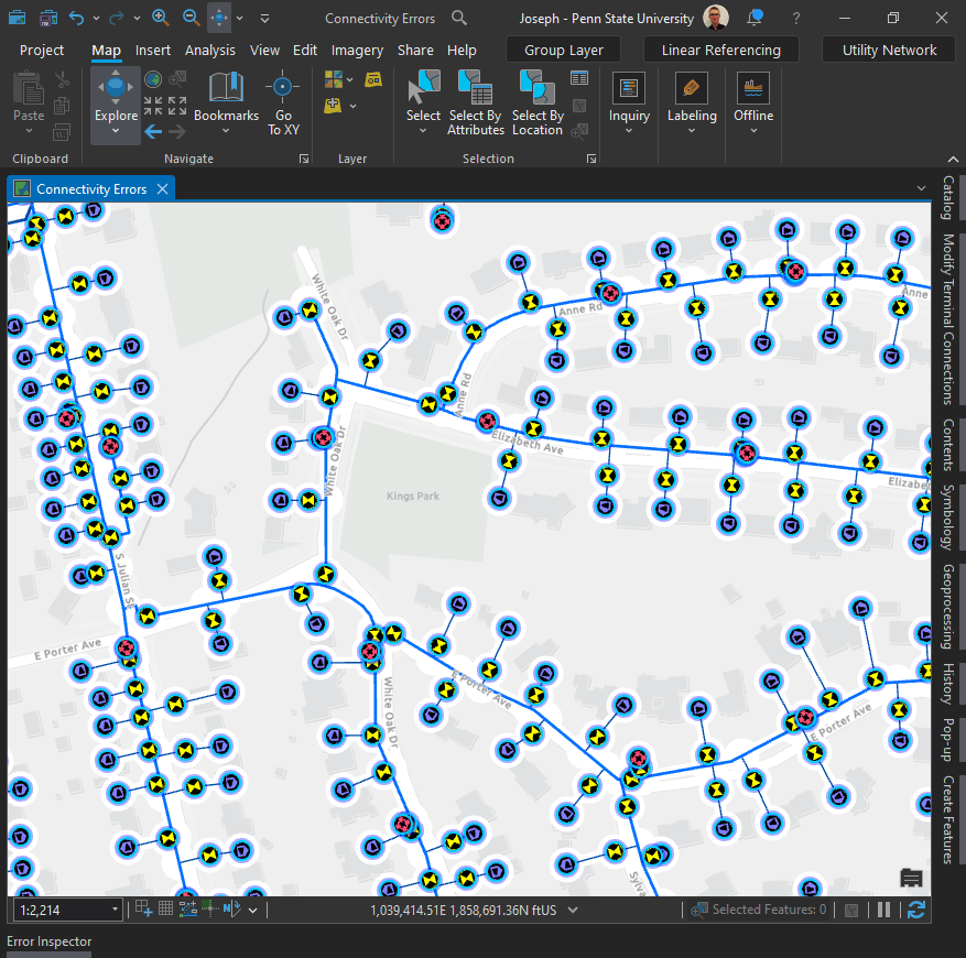
If you are interested in getting started with the Utility Network, one great place to start is the following blog article: Learning about the ArcGIS Utility Network (esri.com). It will will provide links to digging deeper into each domain (industry).
- Getting started with the ArcGIS Utility Network series (other)
- Learn ArcGIS Utility Network for Electric Utilities
- Learn ArcGIS Utility Network for Gas and Pipeline
- Learn ArcGIS Utility Network for Water Utilities
Utility Network Foundation Solutions:
Another geat place to learn is through ArcGIS Solutions. Let’s take a look at Utility Network Solutions for Water.
I would start with the introductory help documentation:
Introduction to Water Utility Network Foundation—ArcGIS Solutions | Documentation
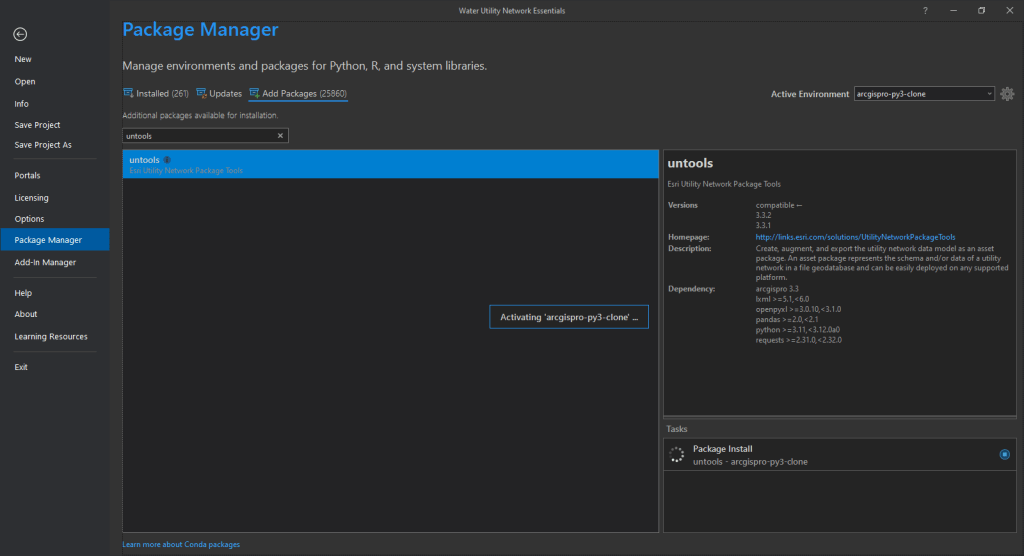
1) Configure data model—ArcGIS Solutions | Documentation : This will lead you how to clone your Python environment (which heads up, might be painfully slow), add the Utility Network Package toolbox, review data dictionaries, and generally become familiar with the model. Just as as warning, you might not be able to add the Utilitiy Network through the Package Manager – Add Packages menu in ArcGIS Pro. In that case, you must use Python Command Prompt (this explanation will help). Basically you need to navigate to your cloned environment and type: conda install -c esri untools –insecure (again heads up that this might be painfully slow).
2) Configure utility network environment—ArcGIS Solutions | Documentation will lead you through how to prepare for implementation of the utility network and the steps below to create a single-user environment.
- Use the Change Asset Package Spatial Reference tool to copy the schema of the asset package, adjust the spatial reference, and generate a new asset package without data.
- It is not required to load or sketch the extent of your data into the ServiceTerritory class in the asset package, but it is good practice and simplifies future steps.
- Load data into the asset package.
- Use the Asset Package to Geodatabase tool in the Utility Network Package Tools toolbox to create a geodatabase, stage the utility network and apply the domain network or networks, related layers, and related tables.
- Included with the Water Utility Network Foundation solution is a map titled Water Essentials Network Asset Types. This map allows you to explore the asset types and asset groups associated with the asset package. It can also act as the starting point to create an editing map. Use the steps below to help you expand the map to fit your organizational needs.
- Add the utility network topology
- Add validation classes
- Use provided data reviewer rules: The Essentials asset package includes a set of predefined data reviewer rules. These rules are meant to be a starting point for checking data migration and used prior to the enabling of topology. If the model was extended or changed, the rules may need to be adjusted or changed. See the Data Reviewer documentation for additional information on how to use these rules.
- Enable topology: The network topology for a utility network is enabled using the Enable Network Topology geoprocessing tool.
- Adjust symbology and pop-ups: The Water Essentials Network Asset Types map comes with a predefined set of symbology and pop-ups for the Essential model.
- Configure utility network map layers.
- Add industry attribute rules.
Trace:
The utility network offers several different types of trace. What are they and why would you want to do a trace in the first place? There might be several reasons.
Here is an excellent article that runs throug the different types of trace: Utility network trace types—ArcGIS Pro | Documentation. I’ll come back to that in a moment, but it might be helpful to see an example first.
Reasons for an Isolation Trace:
- Main Break: One of the most common reasons is that we have a main break and want to know which valves need to be turned off to isolate it.
- Isolated Features: As part of the parameters, we can include the isolated features (like service connections). I’ve added a field for addresses, so when we include those, we can easily export the impacted addresses to send out notifications.
- Checking Results: Let’s say we know which valves to shut off, but we want to run this trace to check if we’re getting the expected results—placing these checks on our GIS could be another reason.
It’s also quite important that you understand the Utility Network Solution Categories. This is important because we’re going to use that tag to stop the trace when it reaches a valve with the category “isolating.”
Utility Network Categories:
- Categories are basically tags—a property that describes a feature and what that feature represents. They can be used as part of trace configurations.
- This is the data dictionary that comes with the utility network solution. If we expand categories, we can see a category called “isolating.”
- Clicking on “isolating,” we can see that the category is used in water device and system valves. Further, we can see the various asset types to which that category is applicable.
- Again, this is important because we’re going to use that tag to stop the trace when it reaches a valve with the category “isolating.”
Running the Trace:
- Start the trace by picking my starting location, zooming in, and clicking on the main. Then, choose “Isolation” as your trace.
- This opens the geoprocessing trace pane. Here, we see our utility network and the isolation trace populates when you chose it from the menu gallery. We could choose a different trace type if desired.
- We have our starting points and barriers. For the domain network, we’re using just the water system.
- There are various parameters and checkboxes checked by default, including containers, content structural attachments, and validating inconsistency.
- Validating Inconsistency: This one’s important—if you’ve done any edits and haven’t validated your topology, the trace will fail if this box is checked. Keep it checked to ensure my network is clean and edits follow the rules you’ve set out.
Traversability vs. Connectivity:
- Connectivity: A state where two or more features are connected, either through a connectivity association or geometric coincidence.
- Traversability: A state where those connected features also have a path between them, satisfied by the trace.
- These were set up as defaults during the sub-network definition, but you can delete or add more condition barriers as needed.
Filter Barriers for Valve Isolation:
- In order to set up a filter barrier using categories and network attributes.
- Starting with our category, the operator is set to “equal to,” and we’ll choose “isolating” as the value.
- Leaving everything else as is, run the trace.
- See here for more: Connectivity and traversability
Results and Isolated Features:
- We see two selected features. Zooming out, we can see which valves need to be shut off.
- Let’s include the isolated features and rerun the trace. Now, it includes everything within the isolated area.
- Clicking on “Select,” we see 100 devices affected and 46 service connections. These 46 residences will be impacted.
- I created a field with service addresses, so I can easily export this to Excel for a list of addresses.
Building on Filters:
- Let’s say we know a valve has been paved over and isn’t operable. We want to ensure operable valves are selected during isolation traces.
- Adding another filter barrier, we’ll choose a network attribute where “operable” is equal to “true.”
- It’s important to use an “AND” statement—not “OR”—so the valve must be both “isolating” and “operable.”
- Running this trace without including isolated features shows that the trace bypassed the inoperable valve and identified the next set of valves that need to be turned off.
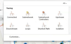
Trace Types:
In ArcGIS Pro, utility networks offer various trace types to analyze network connections and behaviors. Some traces use subnetwork definitions, which are predefined settings based on network tiers, while others don’t.
Subnetwork-Based Traces:
- Subnetwork Traces: These identify all features within a specific subnetwork, starting from a point and finding controllers that manage flow.
- Subnetwork Controller Traces: These locate controllers that manage subnetworks.
- Upstream/Downstream Traces: These identify features in the network based on flow direction, either toward or away from controllers.
- Isolation Traces: These find the minimum set of operable features, like valves, needed to isolate an area in the network, such as in case of a leak.
Non-Subnetwork-Based Traces:
- Connected Traces: These trace connections starting from a point, stopping when barriers or the end of the network is reached.
- Loops Traces: These detect loops where network flow is ambiguous.
- Shortest Path Traces: These find the shortest path between two points, based on attributes like distance.
For accurate tracing, it’s essential to ensure the network is clean and free of errors, especially when dealing with subnetwork-based traces. Advanced configurations can refine trace results based on specific conditions, like finding only certain types of valves or paths.
The following video is quite dry, but it might help provide a bit more context.

Leave a comment